

Pulse miss (int) generally occurred when there is a pulse error occurred on the built–in Pulsecoder.


Condition: Built-in pulse coder degradation or vibration-induced signal disruption resulting in SV 366: PULSE MISS(INT) /SV 367:COUNT MISS (INT) generation.
- Pulse Miss: It indicates a mismatch between the commanded motor position and the actual position reported by the encoder.
- Count Miss: The control system is expecting a certain number of pulses from the encoder to indicate a specific amount of movement, but it’s not receiving that count. It’s like the encoder is losing track of its own movement.
- INT: This specifies the alarm is related to the internal pulse coder, which is typically integrated into the servo motor.
Diagnostic Protocol:
Step 1: Operational State Assessment
Establish the operational context in which the alarm is being generated. Issue an RPM command to the servo motor and verify that the motor rotates at the commanded speed. If the motor maintains the specified RPM, proceed to determine whether the alarm manifestation occurs under dynamic load conditions.
In such scenarios, mechanical vibration transmitted to the servo motor encoder assembly may induce signal discontinuity, resulting in pulse miss detection.
If the alarm is triggered when the axis is in a standstill condition, proceed by checking the built-in pulse coder or interchange it with a similar encoder to verify whether the encoder is malfunctioning.
Step 2: Feed Rate and Spindle Speed Verification :Conduct a comprehensive evaluation of the programmed feed rate and rotational speed parameters for the affected axis. Systematic adjustment and optimization of these parameters are critical mitigation strategies to attenuate mechanical vibration characteristics. Precise calibration of feed velocity and angular velocity within manufacturer specifications will facilitate reduced vibrational amplitude and contribute to improved servo system stability.
Step 3: Mechanical Assembly Integrity Assessment: Execute a thorough mechanical inspection of the entire axis assembly, including all coupling elements, bearing preload conditions, ball screw mounting interfaces, and structural fastening components. Verify that all mechanical connections maintain appropriate torque specifications and demonstrate no observable play or slack that would compromise system rigidity.
Step 4: Vibration Transmission Mechanism Analysis: Mechanical assembly looseness or deterioration in structural integrity can manifest as resonance conditions that propagate through the machine structure. When such mechanical vibration is transmitted to the motor encoder sensor system, it causes erratic signal detection and subsequent loss of synchronization between commanded and actual position feedback. This desynchronization phenomenon directly triggers the SV 366: PULSE MISS(INT) alarm condition. Therefore, elimination of mechanical compliance and restoration of assembly tightness are essential corrective measures to restore encoder signal fidelity and servo system functionality.
Step 5: Encoder Cable Integrity Verification
Prior to performing built-in pulse encoder diagnostics, conduct a preliminary verification of the motor encoder signal cable. Inspect for physical damage, insulation degradation, connector corrosion, or intermittent contact conditions that may simulate encoder signal loss.
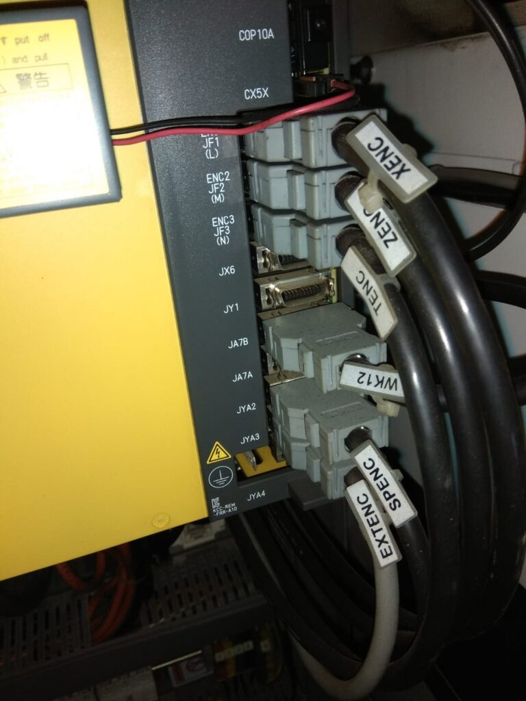
Each axis servo motor encoder is represented by JF. In above image JF1 represent built in encoder cable connector of X axis.JF2 represent built in encoder cable connector of Z axis & JF3 represent built in encoder cable connector of Turret axis.
This may differ by Machine Tool Builder.
Step 6: Built-in Pulse Coder Inspection and Analysis
Upon confirmation that pulse miss alarm does not correlate with operational load conditions, proceed with built-in pulse coder inspection. If encoder position feedback is not displaying on the controller display interface, the pulse coder housing must be opened for internal inspection. In such cases, the optical glass scale component of the servo motor encoder may have sustained mechanical damage or contamination.
Critical Safety Notice: Disassembly and repair of servo motor built-in pulse encoder assemblies must be performed exclusively by qualified technical personnel with specialized training in precision encoder mechanics and optical system alignment.
Disclaimer :The blogs shared on CNC machines are created purely for *educational purposes*. Their intent is to help readers understand CNC controls, alarms, diagnostics, and general troubleshooting methods. We strictly avoid any copyright violations, and all explanations are written only for learning and knowledge-sharing.
These blogs should not be considered as official repair or service manuals. For detailed instructions, critical repairs, or advanced troubleshooting, it is always necessary to contact and work under the guidance of the respective *machine manufacturer* or *CNC controller support team*.
The content provided is focused only on *diagnosis and awareness*. We do not take responsibility for any kind of damage, error, or malfunction that may occur if someone directly applies the information shared here without proper technical supervision.#
Blogs written by the author is very supportive to me.I have solved many problems after reading these blogs.
Really blogs are very good .